For many children with physical disabilities, playing with off-the-shelf toys is not possible. Depending on their unique abilities, a toy may not be accessible.
However, if a child can move their foot, head, arm, mouth or any other part of their body, it is possible to add an accessibility switch (or switches) to the toy so that they can play with it. Accessibility switches come in a variety of styles and can be actuated by different body parts and varied motions.
See enablingdevices.com/catalog/capability_switches/best-sellers for some great examples of accessibility switches.
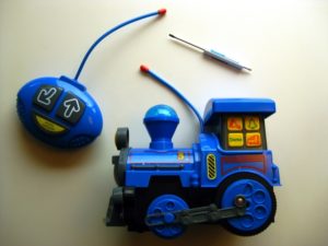
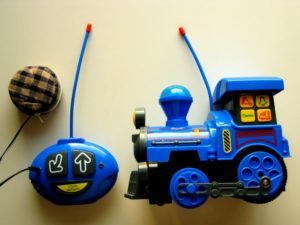
The toy adapted for this instructable is a 2-button remote control train. We will add two switch jacks to the remote control unit so any type of accessibility switch can be swapped in to control the toy. For example, if a child is able to move both their mouth and their left foot, a mouth switch and foot switch could be plugged in so that they could use this train to chase their cat.
Adding switch jacks to this toy will not affect the original quality of use – the existing buttons will operate as normal.
Choosing a Toy

You will need a toy that has a simple operation. You can ask to test the toy in the store, but keep in mind you want a push button operation or simple joystick control.
The toy train we’ll be using here has a simple 2 button interface:1 button to go forward, another button to go in reverse with a slight turn. Perfect for practicing your locomotive K-turns.
The remote control can be adapted to add a switch interface which would enable switch users to control the toy with their head, feet, eye blinks or any standard accessibility switch.
Side note – adapting a remote control toy is actually easier than modifying a self contained toy (like Tickle-Me-Elmo) because the controller is usually very hackable and self contained toys have to be put back together in a very precise way. So if you’re on the fence about which toy to hack, a cheap remote control car can go a long way.
Here’s a list of toys we’ve compiled over the years that are fun and easy to modify, http://www.amazon.com/lm/RVUIMKWKKARYG/ref=cm_pdp_lm_title_1
Important – Battery Operated Toys Only!!
For switch adaptation safety only purchase and hack battery operated toys.
Toys that plug into the wall via a wallwort are probably converting AC electricity to DC but AC is very dangerous. That said, as you become more experienced with electronics and circuits AC devices can be controlled but we will not discuss those here.
Materials

Once you have a toy and have accessibility switches appropriate for the child for whom this is intended, you’ll need a few more items.
Screwdriver
You’ll need the correct sized screwdriver, or in some cases an allen wrench, to open the toy up.
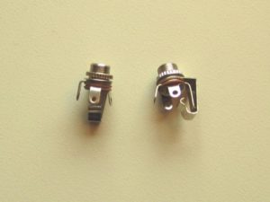
3.5mm mono jacks
We’ll be using 3.5mm mono jacks as our switch jacks. You’ll need one mono jack for each of the toy’s controls. 3.5mm mono jacks accept standard accessibility switches. They can be purchased online at All Spectrum Electronics (if that link doesn’t take your directly to the part, it’s part # CA015).
Each mono jack has 3 tabs that can accept soldering. We’ll be soldering wires to the tabs on the left and right side. The middle tab will remain empty – it is a third connection that is not needed.
Alternatively, you can also use a stereo phone jack from RadioShack and use it as a mono jack – just use a multimeter to test pin connectivity. This should be part #274-0249.
Other stuff
- 22 gauge wire – solid core or stranded – usually 6″ per switch, but this varies depending on the shape of the interface
- Pair of wire strippers
- Soldering iron with lead free solder
- Drill and drill bits – 1/4″ drill bit will fit the 3.5mm, and a smaller drill bit can be used to pre-drill the plastic for the 1/4″ bit.
- Multimeter – Not pictured but needed if you want to verify circuit connections. If you don’t have one, this can be accomplished by using the 22 gauge wire. Have each end touch the solder pads. Once the circuit is completed the toy will turn on.
Opening the Toy
Remove All Screws
Since we are only adapting the remote control unit of the toy, only the remote’s shell will need to be opened.
Don’t be scared, voiding your product’s warranty is exhilarating.
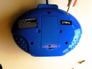
Remove the Battery
It’s good practice to remove the battery from any device you’re going to work on, especially when you’re connecting additional components.
Remove the Controller Lid
Place all the screw in a spot that won’t spill or roll away. Or stick them together with a piece of blue masking tape.
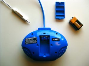
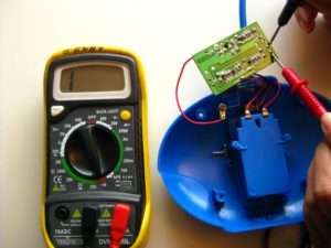
Photo showing battery and screws removed from toy.
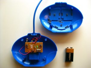
Photo shows toy opened revealing circuit board inside. Screws can be held in the removed lid of toy for safe keeping.
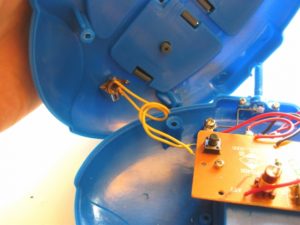
The Circuits and Switches
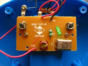
When you open the case of the remote you will see a circuit. Depending on the toy, it can be very simple or a bit more complicated.
In the toy train we’re adapting now, the two black push buttons are the circuit’s switches. The remote control’s plastic switches (the ones with arrows top shell of controller) sit directly on top of these internal switches. When the cover switch is depressed, these internal switches are also pressed and trigger the toy’s functions.
We will be soldering one switch jack to the backside of each of the push button switches.
Detach the circuit from the plastic shell
If you can not access the push button’s solder pads, you will need to remove the circuit from the plastic shell to get underneath the circuit board. Look for some screws on the circuit board and unscrew them.
Place screws in an area where they will not roll away. Finding replacement screws that fit is a pain and it is important that the circuit is replaced correctly once the switch jack is installed.
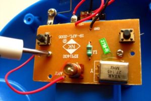
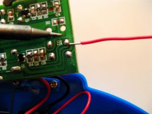
Next we’ll need to locate the 2 pins that “connect” when the push button switch on the circuit board is pressed. It’s those two points were we’ll be soldering the leads of the switch jack.
A multimeter can be used to determine connectivity. Put your multimeter into “connectivity” mode – it’s usually denoted by something that looks like the “increase volume” symbol. Your multimeter should beep and change it’s numeric value when you touch the red and black leads together. The beep and number change indicates that electricity is making it out of the black lead into the red lead and back into the device.
We will only need to determine how the push button switch’s pins are connected, which pins become connected when the push button switch is pressed and which solder pads are connected to which pins.
Flip the circuit over and you’ll see the traces and connections from all the components. Locate the backside of the push button switches. On this particular toy, there are 4 solder pads per switch.
Once you’ve located the switch, with some finger gymnastics touch one lead of the multimeter to a solder pad and the second lead to another solder pad of the switch. Now, press the switch with your thumb. if your multimeter beeps that means you successfully found the two points that connect to make your toy operate this switch’s function.
If your multimeter does not beep or change it’s numeric value on the digital display, Check to see if your leads are touching the solder pads correctly and test that your multimeter is operating as expected.
Your toy may have another style of internal switch that is different from the 4 pin push buttons we had here, but you can use the same process to determine the pins where you’ll need to attach your switch jack.
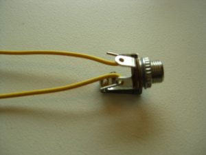
Preparing the Switch Jacks
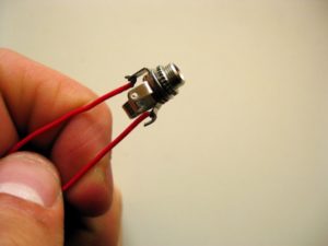
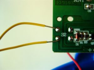
Now we will wire up the switch jacks. In this example, I used yellow wire for one switch jack and red wire for the other switch jack.
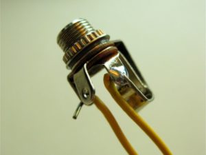
The finished jacks should look like the first photo in the step (with two wires soldered firmly to the jack).
Note that this particular jack has 3 metal tabs, each with a hole. You will be attaching wires to the tabs on the left and right side only (the middle tab is not used).
With the wire stripper, remove a small piece of the plastic sheath. Bend the stripped wire into a little hook.
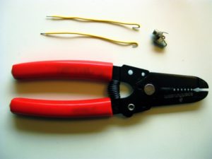
Put the stripped wire hooks into the tabs of the switch jack. The hook in the wire will help keep the wire in the jack when you go to solder it.
You can use helping hands (alligator clips) to hold the wire and jack while you take some solder and your iron to fill in the hole of the tab.
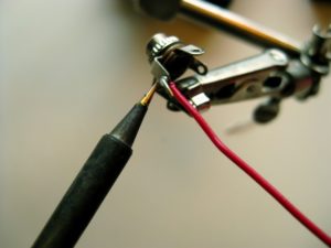
A finished switch jack will not have too much solder and will appear smooth. You should wiggle the wire and see if it is soldered firmly to the jack’s connector. If it wiggles at all you must reheat the solder joint and fill in any visible gaps or holes that exist.
The wires should be attached firmly and should not wiggle.
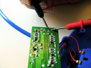
Soldering the Jacks to the Circuit
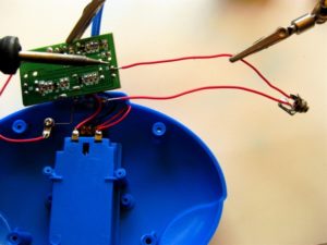
Next we need to solder the leads of the switch jack onto the solder pads of the switch pins we located with the multimeter in step 5.
By soldering the switch jack onto the solder pads of the existing switch, you are simply adding a second switch to the circuit.
Using helping hands or tape, position the wires of the switch jack to overlap the existing solder pad and solder them together.
Do the same to the second solder pad and continue to connect up the other switches on the circuit.
The finished soldering project will be a solid connection between the circuit and your switch jack wires.
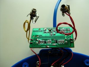
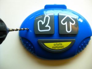
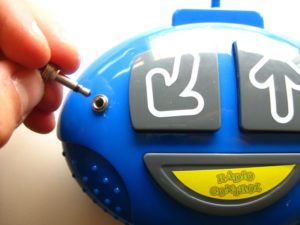
Drill and Mount Jacks
The 3.5mm switch jacks will probably include a circular nut that is screwed to the top of the jack. Drilling a hole in the toy’s case you can insert the jack from the inside and screw it tight from the outside of the case with this circular nut.
Before you make the jack hole, you should predrill the case with a smaller bit to make the hole. Any bit smaller than 1/4″ should be fine.
Hold tight to the case or better yet clamp it to your work bench. With goggles on, drill carefully into the toy’s case.
Once the initial hole is made, take the 1/4″ drill bit and make the final jack hole. You may need to scrape off plastic bits from around the hole.
When hole is clean and open, insert the switch jack. On the outside of the plastic case, screw the jacks tight with the circular nuts.
Final Test and Done
Once all the switch jacks are installed, you can close the case. Be sure the case “snaps” together correctly and that none of the new wires are interfering with the original operation of the physical switches.
Do not screw toy back together yet. Replace the battery into the toy.
Take any accessibility switch and plug it into your toy. Turn on your toy and controller and press the switch.
If your toy is operating incorrectly, for example, it is ALWAYS ON, remove the case and try to locate any area that might be pressing on the switch. Sometimes the contact points for the physical switches inside the case are very small and need to be repositioned correctly.
If your toy is working successfully, replace all the screws and pat yourself on the back! You just successfully adapted a toy!
One thought on “Switch Adapting a Remote Control Toy”
Hi, thanks for sharing this awesome article with us. My son is 6 years old. This is really inspire me. My son will be very happy.